Tuesday, December 14, 2010

Engineering Lab Attracts and Motivates Students

One of the items that I love about my work at Quanser is the opportunity to visit very exciting research and teaching labs at universities and colleges throughout the US and Canada. Each one has something interesting to show – an interesting engineering teaching lab, an advanced research project, or both. One recent trip took me to Colorado and I can’t help but share my amazement with the University of Colorado at Boulder’s Integrated Teaching & Learning Lab (ITL Lab). It’s a perfect example of hands-on, engaging learning - the kind Quanser has been preaching schools to adopt.

Derek Reamon, co-director of the ITL Lab, discussed with me the 34,000 square-foot facility dedicated to engineering. It felt like visiting a science center. Equipped with cutting-edge technology – Quanser’s SRV02-based rotary experiments among them - the lab serves students from the first year to sophomore level, and courses from design and build, invention and innovation to senior design projects. Using a highly effective system, each engineering department can order experiments for their courses from an online catalogue and book a time to work with the selected experiments. The ordered system can be easily wheeled to workstations – at the ITL Lab or anywhere on campus – and ITL Lab’s staff is available to set it up.

The ITL Lab is one of the most attractive features of the engineering school at the UC Boulder. Plus, the university saves space and financial resources, as the same equipment is not duplicated in the labs of each engineering department. The novel approach to learning gained the ITL Lab awards and recognition from the National Academy of Engineering as well as from industry leaders such as Boeing and Hewlett Packard.

My notion of the ITL Lab similarity to a science center is not just co-incidental: every year, thousands of K-12 students and teachers visit to participate in hands-on, ears-on and minds-on K-12 engineering camps, events and workshops. The staff of the ITL Lab also visits schools in the area to talk and demonstrate science and engineering and spark the interest of the future generation in these subjects.

Many other universities adopted the concept of the integrated multi-disciplinary labs serving several engineering departments. If you are looking for the inspiration, let us know – we can put you in touch with one close to you.

- Leor Grebler

Sunday, December 12, 2010

Teach Control Virtually Anywhere with New Text from Norman Nise

Control Systems Engineering by Norman S. Nise is the most wildly adopted textbook for core control courses in mechanical, electrical and other engineering programs. The sixth edition, which is releasing in 2011, offers a dynamic new feature: 10 virtual experiments from Quanser. The experiments are powered by LabVIEW and allow students to manipulate Quanser's simulated lab plants and view realistic response behavior. The virtual experiments will help deepen students' homework learning experience and help them prepare for the actual lab work.

For a limited time, you can request a complimentary copy of the text. But first, here's more information about the virtual experiments supplied with the textbook:

Automobile Suspension allows to explore the dynamics of a two degree of freedom system — an automobile suspension system driving over a bumpy road — demonstrated with the Quanser Active Suspension system modeled in LabVIEW.

With Open-Loop Servo Motor students can explore the dynamics of the Quanser Rotary Servo system modeled in LabVIEW. It is particularly important to know how a servo motor behaves when using them in high-precision applications such as hard disk drives.


Rotary Inverted Pendulum simulates the linear and non-linear model of the Quanser Rotary Inverted Pendulum in LabVIEW. The behavior of an inverted pendulum is similar to a variety of systems, such as Segway transporters and human posture.

First-Order Open-Loop Systems teach students how to find a first-order transfer function representing the Quanser Rotary Servo, then validate the model by simulating it in LabVIEW. Servo motors are used in mechatronic gadgets such as cameras.

Second-Order System Response experiment allows to observe the effect that natural frequency and damping ratio have on controlling the speed response of the Quanser Linear Servo in LabVIEW. The concept is applicable to automobile cruise control or speed control of a train or subway.


Position Control Gain Design teaches how to design the position control gain for the Quanser Linear Servo and simulate its closed-loop response in LabVIEW. This concept is used, for instance, to control a rover exploring the terrain of a planet.


With the Stability experiment students learn how to evaluate the stability of the Quanser Linear Inverted Pendulum in LabVIEW. When in the upward balanced position, this system addresses the challenge of stabilizing a rocket during take-off. In the downward position it emulates the construction gantry crane.

Steady-State Error
experiment teaches how to find the steady-state error of the Quanser
Rotary Servo when subject to an input or a disturbance by simulating it in LabVIEW. This analysis becomes important when developing controllers for bottle labeling machines or robot joint control.


PD Controller Design
experiment uses root-locus to design a PD controller for the Quanser
Ball and Beam using LabVIEW. The Ball and Beam is an unstable system, similar to exothermic chemical processes that have to be stabilized to avoid overheating.


Improving Transient Response and Steady-State Error Using Rate Feedback and PI Control
teaches students how to design a compensator in LabVIEW that controls the ball position in the Quanser
Magnetic Levitation system. Magnetic Levitation technology is used for modern transportation systems that suspend, such as the high speed Magnetic Levitation train.


The new edition of the text is published by John Wiley and Sons and will be available for purchase through them in 2011. If you would like to review a complimentary copy of the text, please contact us at info@quanser.com. For more information about Quanser's real control plants and modules, please visit our website.

Wednesday, December 8, 2010

Stateflow with QUARC

At Quanser I am always looking to find new ways to make it easier to use our variety of products. As I developed controllers for the Quanser Qball-X4 Unmanned Aerial Vehicle (UAV) I found myself building large, complex models in order to create sophisticated, autonomous controllers. Designing a fully-autonomous controller for a complex system such as a UAV requires many considerations and safety checks to ensure the system operates safely and as it should. For example, at the start of a mission there are various initialization procedures and safety checks that occur. Then, the vehicle enters into a controlled takeoff. Next, the vehicle executes the various tasks that make up its mission. And finally, the vehicle performs a landing and power down.


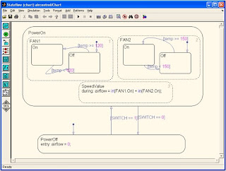
These complex sequences of operating modes and transitions between modes requires careful planning and design. The most suitable design structure for this would be a state machine. Well, as I found out first hand, Simulink (although great for realt-time control) is not the best tool for designing state machines. Thankfully, The MathWorks has a blockset called Stateflow, which allows you to insert state machine charts directly into a Simulink model. The Stateflow chart gives you a graphical design environment different from Simulink and designed for state machine development.


Using Stateflow, I can develop state machines easily and quickly. Stateflow also supports code generation (with Stateflow Coder), so that I can generate code and download it to my target of choice (e.g., Gumstix with QUARC). I can also see graphically at run time the execution of the state machine and which states are currently active. Stateflow expands on the traditional Mealy/Moore state machines and provides useful tools such as temporal operators, Embedded MATLAB Functions, Simulink Functions, variables, events, and support for C-code.


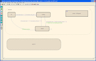
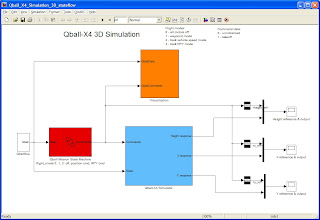
In my application, the Qball UAV mission controller, I chose to divide my model into two parts: Stateflow chart and Simulink controller (although the Stateflow chart resides within the Simulink model as a block). In my Stateflow chart I put all of my state machine logic, operating mode/state, temporal operations, safety checks, etc. In my Simulink controller I build my continuous time controllers, plants, communications, and hardware-in-the-loop interfacing. This is just my preferred design methodology. This allows me to decouple my state machine and safety checks from the Simulink model, which makes extending and maintaining the model a whole lot easier. Now, my controller is not burdened with safety checks and operating mode checks dispersed throughout the model since it is all concentrated in my Stateflow chart.


In my final design, I have my main state machine that allows me to arm and disarm the Qball, schedule autonomous tasks such as waypoint tracking, automatically handle transitions between TAKEOFF, FLY, and LAND operating modes, and also concurrently monitor various safety checks. If at any time a safety check fails or timeout occurs, a LAND event is generated that forces a transition from a FLY state to a LAND state so that the Qball is forced to land.


At Quanser we see possibilities for using Stateflow in so many of our applications: haptics and telerobotics, unmanned aerial and ground vehicles, simulations and 3D visualization, rehabilitation robots, communications, large-scale integrated systems, vision-based tracking and localization, and many more. I would encourage anyone to take a look at Stateflow and try to find innovative ways to use it in Quanser experiments. Good luck!


Cameron

Monday, December 6, 2010

Body Forward!

This last Saturday somebody enchanted my kids: no need to wake them up or remind them ten times to get ready - they managed everything in a record time. So by 8.15 AM we were wondering around the lobby of the Woburn Collegiate Institute in Scarborough, looking for the rest of the Huron Hawks Team - and their Lego Robot. The day of their FIRST Lego League Qualifying Tournament was finally here.

Huron Hawks getting their Lego robot ready for the tournament.

Woburn Collegiate was like a little hive - full of mostly 4 - 6 graders eager to put their robots into the ring and compete in the FLL's Body Forward Challenge. For many of the kids it was a first venture into the realms of biomedical engineering. Their robots had to fix broken bones, get to a syringe or patch the heart. Plus, they did their own research on an illness they found interesting and prepared a poster presentation. I bet you never heard about the Zollinger Ellison syndrome. Huron Hawks can tell you what's the cause and how it can be treated.

Part of the FLL competition is a project presentation - this year tied to biomedical engineering.

The robot matches were hilarious! While the teams were cheering on the side, two brave robot operators had to cope with the pressure and try to fulfill in 2 1/2 min as many of the fifteen tasks as possible. It was amazing to see what these kids could do!

In the matches, Lego robots have to perform series of tasks in a limited time.

For Mr. Goodyear, coach of Huron Hawks and teacher at the Huron Street Public School, it's all about team work: kids learn how to present their ideas and listen to the ideas of others, how to find roles in the team they can contribute their best and how to work towards a deadline. It's a great way how to capture their interest in science and engineering! Let's see what they will invent in the future!
Two robot operators control the robot during the match, switch the robot arms to make it push, pull or lift various objects.

As a parent, I must express many thanks to teachers, coaches and all volunteers who dedicate their time to bringing this event together. And to Quanser engineers who participate in workshops, career days and competitions and inspire grade- and high-school kids to become engineers too.

Friday, December 3, 2010

Engineers Without Borders

EWB Canada describes their mission as the following:
"Engineers Without Borders" creates opportunities for rural Africans to access clean water, generate an income from small farms, and have improved access to the services and infrastructure they need to improve their lives. We harness the problem-solving approach and creative pragmatism of the Canadian engineering sector to address the root causes of poverty in rural Africa."

While not personally involved with EWB, I am delighted to see that a former classmate of mine is. Wayne Miranda has been living in Ghana since graduation in 2008. While passing on the traditional road a graduate might take, Wayne has chosen a career more noble. Wayne works closely with farmers and politicians alike, trying to bridge the gap between their two worlds and develop sustainable programs that will one day alleviate the chronic poverty that persists in the region.

EWB Canada has recently started a campaign called "The Perspectives Challenge" that aims to raise both funds and awareness. It began on November 15th and will run until December 31st. One important thing to note is that 87 cents of every dollar raised go directly to the programs in Canada and Africa. You can read Wayne's Perspective here, it is both fascinating and admirable. It's people like Wayne and organizations like EWB that make our world a better place. Support Engineers Without Borders. Please donate today.

Monday, November 22, 2010

Improved Mechatronics Control Kit Combines New Technology with User-Friendly Operation

Mechatronics Control Kit - or MechKit - is one of several experiments Quanser offers for hands-on teaching of control. Originally designed by Dan Block and Dr. Mark Spong at the University of Illinois at Urbana-Champaign, it has been popular for several years, thanks to its compact design and selection of control challenges. As technology evolves, the Mechatronics Control Kit needs to keep up. So here are the latest improvements our engineering team came up with to make this lab tool more effective for educators:

New peripherals improve MechKit's performance.
To improve performance of the MechKit, we integrated new peripherals developed by Quanser: our new Q2-USB DAQ and VoltPAQ-X1 power amplifier. Plus swapping modular parts to set up a new experiment is now much easier.

QUARC integration enables rapid control prototyping
Another new feature of the improved MechKit is the interface to QUARC. That makes changing parameters much easier and allows MechKit users to benefit from all the features of QUARC rapid control prototyping software and its seamless integration with MATLAB/Simulink.

More compact design
All above mentioned improvements result in more compact and portable design. Sure, the MechKit got a bit smaller, but it also became more powerful.

You can see the prototype of the Mechatronics Control Kit at the upcoming IEEE Conference on Decision and Control 2010 in Atlanta, Georgia. The new MechKit is slated for release in 2011. For more details, contact info@quanser.com

Computer rendering of the new improved MechKit.

Thursday, November 18, 2010

QUARC Software at the Heart of a Unique Subterranean Lab

Quanser is a proud partner of a unique research project underway in Canada. Toronto Rehab, Canada's largest academic health sciences centre is home to one of the world's most advanced rehabilitation facilities - Intelligent Design for Adaptation, Participation and Technology (iDAPT). The centerpiece of iDAPT is the Challenging Environment Assessment Lab (CEAL), a huge subterranean research lab with a hydraulic motion simulator where researchers can study interactions between people and their environment. To simulate different conditions, such as icy sidewalk, researchers will use large chambers that can be lifted on and off the simulator. Several Canadian companies mentioned in a recent press release lent their expertise to develop CEAL. Quanser's contribution lays right at the heart of the system: Quanser's real-time control software QUARC controls the simulator itself, enables integration of all instruments and ensures safety of the whole system. All signals from the measurement
devices - motion capture camera, force plates etc. are routed through QUARC. High performance and flexibility of QUARC's Stream API and Hardware-In-The-Loop API allow for rapid integration of all these different components. QUARC also monitors and controls all simulation systems in real time and is responsible for real-time reaction models that dictate responses of various interfaces, including the simulator, the treadmill, the visual display and the audio cueing systems. For example, to create a fall scenario on the instrumented stairs, the reaction model might specify that as soon as the participant exerts a particular force on a particular step, the simulator will be accelerated rapidly. The latency of this process, from measurement system output to simulation system input is less than 25ms.

"The power of QUARC, with Quanser's engineering support," said Dr. Geoff Fernie, Toronto Rehab's Vice President in the interview earlier this year "enabled us to create a flexible development environment for researchers to implement sophisticated real-time experiments, using a large scale 11-ton, 6-DOF motion platform and high-performance audio-visual rendering system. "
To discuss your unique research lab needs, contact info@quanser.com

Monday, November 15, 2010

12 Things You Should Know About UVS

Quanser's unmanned technology got a lot of attention this summer. Delegates at the ASEE Annual Conference, ACC 2010 and AIAA Guidance, Navigation and Control Conference had an opportunity to experience the Unmanned Vehicle Systems Lab and fly Quanser's Qball-X4, an unmanned aerial vehicle. Students and professors asked our engineers many great questions about applications, sensors, cameras and batteries. We captured the technical questions and summarized answers for you.

What is the payload of the Qball-X4? The Qball-X4 can carry up to a maximum of 400 g, but since more weight reduces flight time, we recommend payloads of 300 g or less. This is an important consideration when adding sensors to the Qball.

What kind of sensors come on the Qball-X4? The main sensors on the Qball-X4 are:

  • 3-axis gyroscope
  • 3-axis accelerometer
  • 3-axis magnetometer
  • Pressure sensor

These on-board sensors are used to primarily stabilize the vehicle. In addition, they can be used for obstacle avoidance missions.

What are the OptiTrack cameras for? The OptiTrack cameras are for tracking the position (XYZ) of the vehicles (multiple vehicles if desired) in the lab workspace. They function as indoor GPS but with much higher sampling rates (up to 100 fps) and much higher accuracy (on the order of 1 cm or less). The cameras are not strictly necessary to fly the Qball-X4, but are an integral component of the lab. These cameras are important for performing autonomous missions as they provide the position feedback (XYZ) that is not measurable by the Qball-X4’s on-board sensors directly.

Can I mount the OptiTrack cameras on the Qball-X4 or another vehicle? The cameras must be mounted in fixed positions in your lab space and calibrated. They should not be placed on the Qball-X4 or Qbot vehicles.

Can I use different cameras? Since the system is modular, it is easy to swap out the OptiTrack cameras for another localization system provided the new system is interfaceable to Simulink®. Quanser’s technology also supports VICON cameras.

What kind of batteries are used on the Qball-X4? How long can the Qball-X4 fly? We use two LiPo (Lithium Polymer) batteries on each Qball-X4, which allows up to 15 minutes of continuous flight. The full battery recharge for the next flight takes app. 45-60 min. Each Qball-X4 is supplied with a spare set of batteries and a recharger.

Can the UVS Lab be used to run multiple vehicles simultaneously and how do they communicate? Yes, the UVS Lab is designed to run multi-vehicle missions simultaneously. Since each vehicle is equipped with its own embedded Gumstix® and HiQ DAQ, multiple vehicles can be deployed using WiFi. Due to the nature of Simulink, a controller (Simulink model) can only be run on one target (Qball-X4) at any given time. Thus, to run multiple vehicles, multiple Simulink models have to be created and each model needs to be targeted to a specific vehicle. The on-board Gumstix computer is equipped with WiFi 802.11g and the QUARC software included with the UVS Lab allows to communicate wirelessly (TCP/IP or UDP) between vehicles.

Can I add my own sensors to the Qball-X4? What kind of I/O is available on the Qball-X4? The Qball-X4 DAQ, the HiQ, was designed with additional I/O ports so that other sensors can be easily integrated into the system. Some of the I/O available on the HiQ for use with other sensors are:

  • 6 analog inputs
  • 11 reconfigurable digital I/O
  • 2 general purpose TTL serial ports

The pins are found on the HiQ daughterboard. Once a sensor is connected, these inputs can be read in Simulink using the QUARC HIL blocksets and Stream API. The main consideration for adding additional sensors is whether they:

  • meet payload requirements
  • meet the particular I/O voltage and current requirements.
Can I add a camera to the Qball-X4? Is the Qball-X4 capable of performing image processing? The on-board computer is a 600 mHz Gumstix Verdex with 128 MB of RAM. The computer is designed for low weight, low power consumption and small form factor. It does not have the processing capability to perform significant image processing (greater than 10 fps). The recommended solution for image processing is to use a wireless camera that can stream video to a more powerful ground station computer, which can process the video and stream back the results to the controller (i.e. Gumstix) over WiFi.

Can the on-board Gumstix be replaced with a more powerful embedded computer? The HiQ is designed to interface specifically with the Gumstix Verdex computer and the UVS Lab software QUARC supports only this model of Gumstix. As embedded computer technology evolves, it is likely this lab will support more powerful embedded computers.

Is the Qball-X4 an off-the-shelf helicopter or is it made by Quanser? The Qball-X4 is a helicopter designed and manufactured by Quanser. The HiQ, a high-end DAQ is also designed by Quanser and customized for UVS research.

How much does the UVS Lab cost? Can I buy just the Qball-X4 or do I need to purchase the entire setup? For pricing, please contact our Academic Solutions Advisors at info@quanser.com. You have an option to purchase Qball-X4 or Qbot (unmanned ground vehicle) separately or as a turn-key lab. You can also purchase multiple unmanned vehicles for your lab.

For details on the UVS Lab components, please refer to the Product Information Sheet.

For a UVS Lab demonstration, please contact Sunny Ray at sunny.ray@quanser.com